Instructions for use
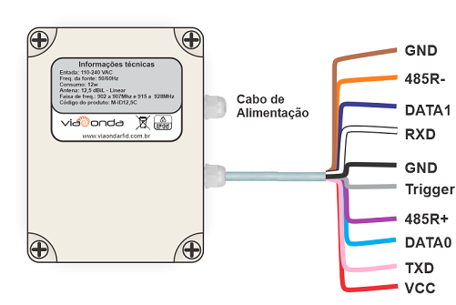
Wire Description
Attention
Use the power supply shipped with the scanner to avoid damage to the hardware of the scanner.
General operating diagram
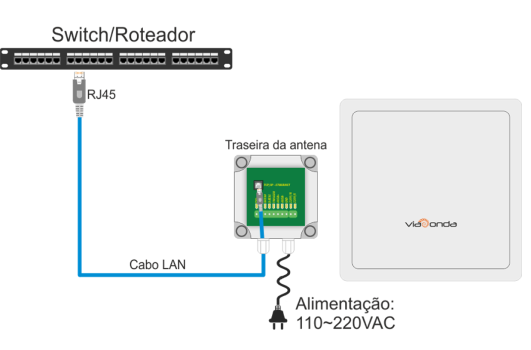
M-ID12L – ETHERNET CONNECTION
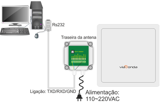
M-ID12L – RS232 CONNECTION
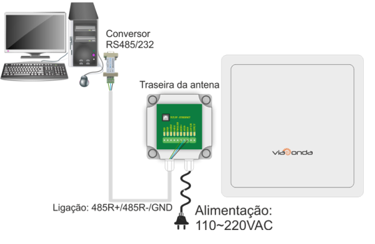
M-ID12L – RS485
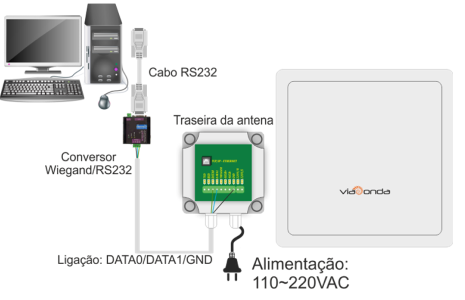
M-ID12L – WIEGAND
The diagrams presented above demonstrate the standard installations of the M-ID12L module, through the available interfaces: Ethernet, RS232, RS485 and Wiegand.
When turning on the M-ID12L for the first time, it will be in factory operating mode as described in the technical specifications.
When turned on, a red LED lights up on the back, indicating that the equipment is powered, on the front a green LED lights up when readings are being taken.
Depending on the reader's operating mode, at each new reading, it will automatically send the read tag code in hexadecimal format through network communication, via Ethernet, RS232, RS485 or Wiegand.
Interface to Inputs and Outputs
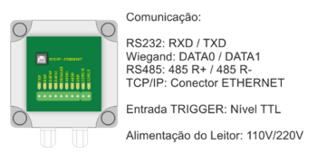
M-ID12L – INTERFACE DESCRIPTION
Reading modes
The M-ID12L allows operation in 3 different modes, namely, slave mode, continuous mode and trigger mode (trigger). Each of the operating modes has specific operating characteristics, which can be better exemplified in the following topics.
Slave Mode (Answer Mode)
When in slave mode, the module waits for the command to start the readings, sends each tag read in hexadecimal format via the chosen communication, and waits for the command to end the readings.
Continuous Mode (Active Mode)
When in continuous mode, the M-ID12L enters uninterrupted reading mode, where it will send each tag read in hexadecimal format via chosen communication.
This module depends on the connection established with the reading software, if communication is interrupted, it enters standby mode again, waiting for the command to restart reading.
Trigger Mode
When in trigger mode (trigger), the module will only enter read mode, when it receives a pulse on the TRIGGER pin in the interface connection. The details of the interfaces can be found in the Inputs and Outputs Interface section. Operating in this mode, the reader, after receiving a signal on the TRIGGER pin, will enter reading mode, and will remain so until the state of the pulse on the TRIGGER pin changes state. For example, if the pulse lasts 5 seconds, the module will read the tags for a period of 5 seconds, waiting for the request to read the buffer, via command, to return the list of read tags, also in hexadecimal format.
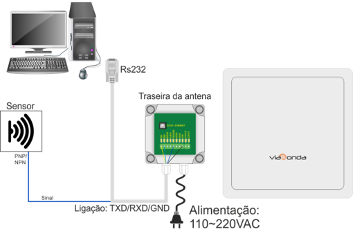
M-ID12L – TRIGGER MODE CONNECTION
TCP/IP Configuration
In this area it is possible to search and configure the reader's TCP/IP properties when it is connected via ethernet.
Configure IP Address
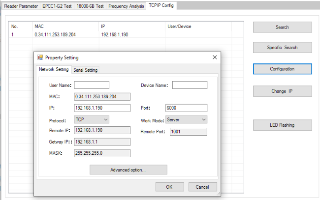
Wiegand Configuration
Standard M-ID12L antenna configuration with wiegand26/34 communication protocol.
- Wiegand Parameter
- Wiegand 26/34: Sets the wiegand protocol to be used.
- Data output interval: Defines regular intervals for data output.
- Pulse interval: Defines the interval between pulses.
- Pulse width: Defines the pulse width.
- Wiegand output LSB/MSB first: Selects the wiegand output format.
- Set Work Mode
- EPCC1-G2: Defines the protocol to be used.
- Storage area or inquiry conducted tags: Defines the memory bank of the tag to be read.
- Wiegand Output: Enables wiegand output.
- Byte Addr: Defines the starting address.
- Buzzer: Enables or disables the buzzer.
- Work Mode: Defines the antenna operation mode (Active/Answer/Trigger).
- Single Tag Filtering Time: Defines the tag reading interval.
- First Byte Addr(HEX): Position of the first byte to be sent.