Instructions for use
Attention
Be sure to use the power supply that was shipped with the player to avoid damage to the player's hardware.
Initial Settings
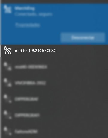
When turning on the M-ID10W BLE-HID for the first time, it will have factory settings, therefore, a new Wireless network will be created and will wait for connections. The network name (SSID) is created by default, being mid10-xxxxxxxx (x = reader's unique identification).
The default password for connecting to Wifi is: viaondarfid
Admin page
Access to the administration/settings page is done through your browser (Google Chrome, for example) through the address: http://192.168.0.10
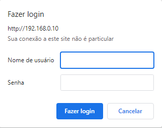
Default credentials are:
- User: admin
- Password: admin
Current data
In this section, the current network configuration data is displayed.

When your model does not have an RTC (Real Time Clock), the message: RTC NOT PRESENT ON THIS BOARD VERSION will be displayed in the Date and Time field.
Wireless Parameters
In this session it is possible to define the Wireless parameters.

- Operation mode:
- Access Point: Defines that the M-ID10W will be used as an access point (like a router).
- Station: Defines that the M-ID10W will be used as a station, and must connect to an existing WiFi network.
In this mode, it is mandatory to fill in the name of the SSID network where the reader will connect, as well as the connection password. The IP addressing parameters must be defined manually, as the configuration does not allow operation in DHCP mode, only with a static IP address.
- SSID: When in Access Point mode, the SSID is automatic. When in Station mode, it is necessary to inform the name of the SSID network where the reader must connect.
- Connection Password: When in Access Point mode, it is the password required to connect new clients. When in Station mode, it is the SSID network connection password where the reader should connect.
The player will try to connect to the provided network for 10 times with an interval of 5 seconds. If it fails to connect, the reader will automatically restart, repeating the connection process.
- Socket Server Port: It is the network port that the reader will open a listener waiting for external connections. It is used when the equipment is operating in Answer Mode mode.
- IP: Static IP of the reader.
- Mask: Netmask.
- Gateway: Network Gateway IP address.
- Operation Channel: WiFi operation channel used by the equipment. (Only in Access Point mode)
- Host: Apply DNS to customize the access link of your reader settings, as shown in the example below.

General Parameters
In this session it is possible to define the general parameters of the equipment.

User: username used to login to the administration page.Password: access password for the login in the administration page.Print RFID TX data on Serial Debug: allows turning on or off the sending of Debug data to the RX2 auxiliary output.Debug Mode: when enabled, it allows debugging the firmware.Save Debug on SD Card: when enabled, it allows saving the debug on the SD card.Keep Alive: when enabled, it allows sending the chosen message to show if there is a persistent connection.
Radio frequency parameters
In this session it is possible to define the RFID working parameters and automatic operation.
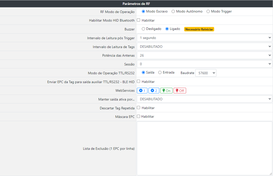
RF Operation Mode: Defines the operation behavior of the RFID reader, being:- Answer Mode: It is used when the equipment must wait for reading commands coming from the DLL library or from the network Socket.
Access http://restrito.viaondarfid.com.br to download the SDK and auxiliary support documents.
- Active Mode: In this mode, the reader automatically enters the reading operation, recording the read tags in the buffer, memory card or sending them to a URL, when configured.
- Active Mode (Trigger): Like the previous mode, in this mode, the reader will wait for a pulse in the input GPIO to perform the reading. This is a standalone read based on a condition.
- Answer Mode: It is used when the equipment must wait for reading commands coming from the DLL library or from the network Socket.
Enable Bluetooth HID Mode: When enabled, configure the reader to send an EPC tag via Bluetooth to a paired device. The Send EPC Tag to auxiliary TTL/RS232 - BLE HID output option must be enabled. The functionalities of the Web services and networks will remain disabled and, to access the configuration page again, it will be necessary to reset the equipment.Buzzer: Enables or disables Buzzer. Need to restart the reader after settingPost Trigger Reading Interval: Defines the time the reader will read after the input GPIO pulse.Tag reading interval: Determines the Tag reading interval time.Antenna Power: Defines the reading power, from 1dBm to 26dBm.Session: Defines the session that will be used in the readings.- Session 0: The RFID tag responds to all requests made by the RFID reader.
- Session 1: When the RFID tag receives the request from the reader for the first time, it responds promptly. After that, the tag enters a state of silence and waits between 0.5 and 5 seconds to respond to the next request. The silence time is not configured, who defines it is the tag itself.
- Session 2 or 3: The RFID tag responds the first time it is detected by the antenna. If it stays close to the antenna, the tag will not respond again. When you leave the antenna range, after up to 20 seconds it will respond again.
TTL/RS232 Operation Mode: Defines the TTL/RS232 operation mode, allowing data input or output. When OUTPUT is selected, data can be collected by serial, EPC of tag turns on can be collected if optionTTL/RS232 Operation Mode: Defines the TTL/RS232 operation mode, which can be data input or output. When OUTPUT is selected, data can be collected via serial, the EPC of the tag on can be collected if the option Send Tag EPC to TTL/RS232 auxiliary output is enabled. When INPUT is selected, it allows the data received on the RS232 input to trigger for the specified time. Autonomous-Trigger Mode must be enabled.Baudrate: Allows choosing the baudrate for TTL/RS232 output or auxiliary input Necessary to restart the reader after definitionSend Tag EPC to TTL/RS232 auxiliary output - BLE HID: when enabled, it sends the readings carried out through bluetooth communication..Web services: Used for GPIO reading and activation operations.See the Web services section for information on collecting and clearing the buffer.
Operation url 
Collect Input GPIO Status 1 http://[IP]:8080/getInput1Status 
Collect Input GPIO Status 2 http://[IP]:8080/getInput2Status 
Turn on Output 1 GPIO http://[IP]:8080/gpio.php?output=1&status=on 
Turn off GPIO Output 1 http://[IP]:8080/gpio.php?output=1&status=off Keep output active for...: When configured in Active Mode or autonomous with trigger, it defines the time in which the digital output will be kept ON after reading the TAG. If the EPC mask is enabled, only the tags that respect the mask will trigger the digital output (with the exception of tags included in the exclusion list.). This time can vary from 0 (DISABLED) to 30 seconds.Discard Repeated Tag: When selected, it discards the repeated reading of the same tag in sequence.EPC Mask: Defines the reading mask. The filter length must be between 1 and 24 digits, and can filter on the EPC prefix or a unique tag. Any other tag that is not inside this mask the reader will completely disregard.Example: If the mask 3034541 is defined, only the tags that have the EPC with the same beginning as the mask will be processed, the others will be discarded
Exclusion List (1 EPC per line): When a tag must be discarded, even if it is within the mask rule, the complete EPC of the TAG (24 digits) that must (must) be discarded can be entered in this list (s).
Firmware update
The equipment will only notify if there is an update if it is in *Station mode.
When an update is available, you can update it through the reader's administration/configuration page. After update, the player will be reset to factory default.

Attention
While the equipment is being updated, it is crucial that it is not turned off and that the internet has a stable connection.
GPIO's
| Type | Description | Standard Status | Drive Voltage |
|---|---|---|---|
| Input | GPIO Input 1 | Off | 5v DC |
| Input | GPIO Input 2 | Off | 5v DC |
| Output | GPIO Output 1 | Off | 5v DC |
Web services
Control of GPIO's
Retrieve digital input 1 status
URL: http://[IP]:8080/getInput1Status
METHOD: HTTP GET REQUEST
PARAMETERS: None
RETURN 1:
{
  "message": "Get GPIO Status Input 1",
  "Status": "OFF"
}
RETURN 2:
{
  "message": "Get GPIO Status Input 1",
  "Status": "ON"
}
Retrieve digital input 2 status
URL: http://[IP]:8080/getInput2Status
METHOD: HTTP GET REQUEST
PARAMETERS: None
RETURN 1:
{
  "message": "Get GPIO Status Input 2",
  "Status": "OFF"
}
RETURN 2:
{
  "message": "Get GPIO Status Input 2",
  "Status": "ON"
}
Change status of digital output 1
URL: http://[IP]:8080/gpio.php?output=1&status=on
METHOD: HTTP GET REQUEST
PARAMETERS: output - Ident. Output (Pattern 1) | status - on / off | timer - Time to keep the output on (in seconds)
RETURN 1:
{
  "message": "GPIO 14 Output turned ON"
}
URL: http://[IP]:8080/gpio.php?output=1&status=off
METHOD: HTTP GET REQUEST
PARAMETERS: output - Ident. Output (Pattern 1) | status - on / off | timer - Time to keep the output on (in seconds)
RETURN 1:
{
  "message": "GPIO 14 Output turned OFF"
}
URL: http://[IP]:8080/gpio.php?output=1&status=on&timer=5
METHOD: HTTP GET REQUEST
PARAMETERS: output - Ident. Output (Pattern 1) | status - on / off | timer - Time to keep the output on (in seconds)
RETURN 1:
{
  "message": "GPIO Output turned ON for 5 seconds"
}
WS BlackList
Add tag to list
URL: http://[IP]:8080/blackList?add=3074257BF4B98CC000000008
METHOD: HTTP GET REQUEST
PARAMETERS: Nenhum
RETURN 1:
{
  "response code": "200",
  "status": "sucesso",
  "msg": "EPC adicionado com sucesso na black list",
  "blackList": "3074257BF4B98CC000000015"
}
Remove tag from list
URL: http://[IP]:8080/blackList?remove=3074257BF4B98CC000000008
METHOD: HTTP GET REQUEST
PARAMETERS: Nenhum
RETURN 1:
{
  "response code": "200",
  "status": "sucesso",
  "msg": "EPC removido com sucesso na black list",
  "blackList": ""
}
List registered tags
URL: http://[IP]:8080/blackList?list
METHOD: HTTP GET REQUEST
PARAMETERS: Nenhum
RETURN 1:
{
  "response code": "200",
  "status": "sucesso",
  "blackList": "3074257BF4B98CC000000025, 3074257BF4B98CC000000028, 3074257BF4B98CC000000023"
}
Clear tag list
URL: http://[IP]:8080/blackList?deleteAll
METHOD: HTTP GET REQUEST
PARAMETERS: Nenhum
RETURN 1:
{
  "response code": "200",
  "status": "sucesso",
  "msg": "Sucesso ao deletar arquivo de black list",
  "blackList": ""
}
Restore to Factory Default
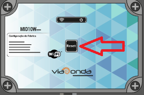
The M-ID10W, It has a reset button when pressed once the equipment will be restarted. To restore factory default follow the steps below.
- Turn off the equipment from the power source.
- With the equipment off, press and keep the reset button pressed.
- With the button pressed, connect the equipment again on power source. Once this is done the equipment will issue a short sound.
- Keep pressing the reset button for another 15 to 30 seconds until emit another longer sound. This will indicate that the equipment has returned to factory defaults.
In current versions it is possible following the step below.
- With equipment on, keep the reset button pressed until it emits a long beep, should occur after 15 to 30 seconds after pressed.
Attention
With factory restore, readings that are saved on the SD card will be deleted.
Restart Reader
Apply equipment reset without affecting settings.
To save
Apply the settings on the player. The configurations are saved in the equipment and are maintained even after it is turned off.
Language
The administration page is available in 2 languages, English and Portuguese. To switch between languages, simply select the desired language flag and the page will refresh automatically.