Use Instructions
Reading mode
By default the M-ID40 Wifi is sent operating in response mode, in this mode it needs commands to start and stop reading, where it will send via wireless network each tag read in hexadecimal format.
This mode depends on the connection established with the Development Software (SDK), if the communication is interrupted, it enters waiting mode again, awaiting the command for reading restart.
It is also possible to use the reader in autonomous mode, in this mode, whenever the reader is started will already have the reading active not being required commands. To change the operating mode, the change must be made through SDK.
Diagrams
General Operating Diagram
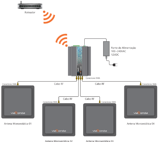
The diagram presented above demonstrate the default installation of the M-ID40 module, with a maximum of 4 antennas, both using the Wifi model. When connecting the M-ID40 for the first time, it will be in factory operating mode as described in factory settings. To change the operating mode, check the Settings page. In order for the reader to operate correctly and read the RFID UHF labels, make sure there is at least one antenna properly connected to the equipment.
Depending on the reader's mode of operation, with each new reading, it will automatically send the tag code read in hexadecimal through the communication method of each model, via Ethernet or Wifi.
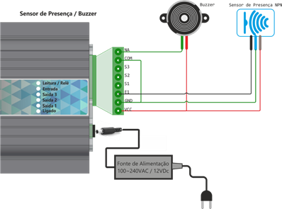
Buzzer Installation Diagram (Signal) and sensor (trigger mode)
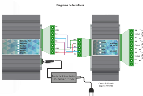
Output installation diagram (With interface M-IDIO3)
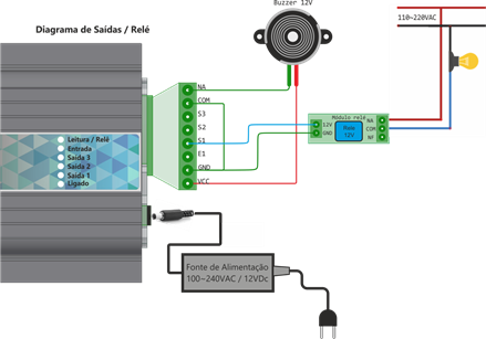
Output installation diagram (Generic)
Rear view
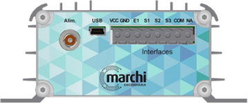
| Identif. | Description |
|---|---|
| Alim. GND | Power input 0v (GND) |
| Alim. VCC | Power input 12Vdc |
| USB | Mini-USB type connector for serial communication with PC (does not accompany cable) |
| GND | Auxiliar output GND |
| VCC | Auxiliar output VCC |
| E1 | 12V Input for Sensor (trigger) |
| S1 | Auxiliar output 1 12Vdc |
| S2 | Auxiliar output 2 12Vdc |
| S3* | Auxiliar output 3 12Vdc |
| COM | Common Input Relé |
| NA | Exit NA Relé |
*Available only in Linux and WiFi versions
Attention
Be sure to use the power supply sent with the reader so as not to cause damage to the equipment.
Front view

| Identif. | Description |
|---|---|
| 1 | Connector SMA of Antenna 1 50ohms |
| 2 | Connector SMA of Antenna 2 50ohms |
| 3 | Connector SMA of Antenna 3 50ohms |
| 4 | Connector SMA of Antenna 4 50ohms |