Use Instructions
Reading modes
The M-ID40 allows operation in 3 different modes, being, response mode, autonomous mode and trigger mode (trigger). Each of the operating modes has specific operating characteristics, which can be better exemplified in the following topics.
- Answer Mode (Slave):
- The M-ID40 Linux needs to receive commands to start or stop reading.
- Autonomous Mode:
- Once configured the reader will always start with active reading, there is no need for a command.
- Trigger Mode:
- In this mode, the module will only enter reading mode when it receives a pulse in input 1 (E1). Operating in this mode, the reader, after receiving a pulse in Input 1, will start reading, and remains so until the state of the pulse in pin E1 changes of state. For example, if the pulse lasts 5 seconds, the module will read the tags for a period of 5 seconds. It is also possible to access the equipment control panel to configure the reading time upon receipt of the pulse.
In all modes, readings are stored in an internal database of the reader and are available for consultation or sending according to the configured method.
Diagrams
General Operating Diagram
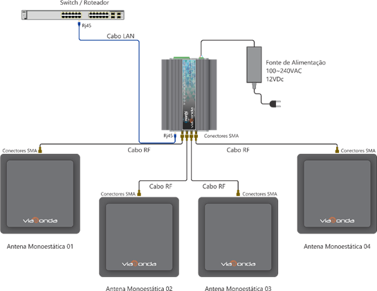
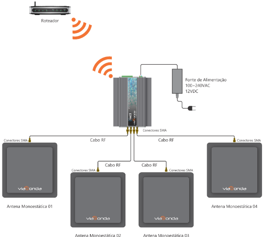
The diagrams presented above demonstrate the default installation of the M-ID40 Linux module, with a maximum of 4 antennas, using both wired and wireless communication. When connecting the M-ID40 for the first time, it will be in Answer Mode. To change the operating mode, check the information in Settings. In order for the reader to operate correctly and read the RFID UHF labels, make sure there is at least one antenna properly connected to the equipment.
Depending on the reader's mode operation and configuration made with each new reading, it will automatically send the tag code read in hexadecimal formed through the communication method of each model, via Ethernet or Wifi.
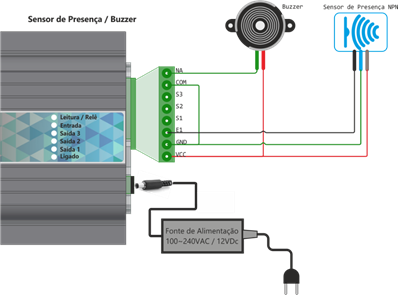
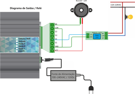
Buzzer Installation Diagram (Signal) And Sensor (Trigger Mode)
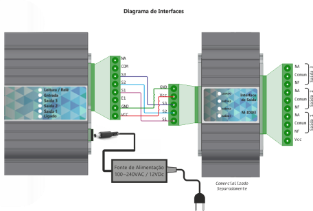
Output installation diagram (With Interface M-IDIO3)
Output installation diagram (Generic)
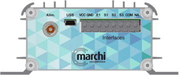
Rear view
| Identif. | Description |
|---|---|
| Alim. GND | Power input 0v (GND) |
| Alim. VCC | Power input 12Vdc |
| USB | Mini-USB type connector for serial communication with PC (does not accompany cable) |
| GND | Auxiliar output GND |
| VCC | Auxiliar output VCC |
| E1 | Input 12V for Sensor (trigger) |
| S1 | Auxiliar output 1 12Vdc |
| S2 | Auxiliar output 2 12Vdc |
| S3* | Auxiliar output 3 12Vdc |
| COM | Common Input Relé |
| NA | Exit NA Relé |
*Available only in Linux and WiFi versions
Attention
Be sure to use the power supply sent with the reader so as not to cause damage to the equipment.
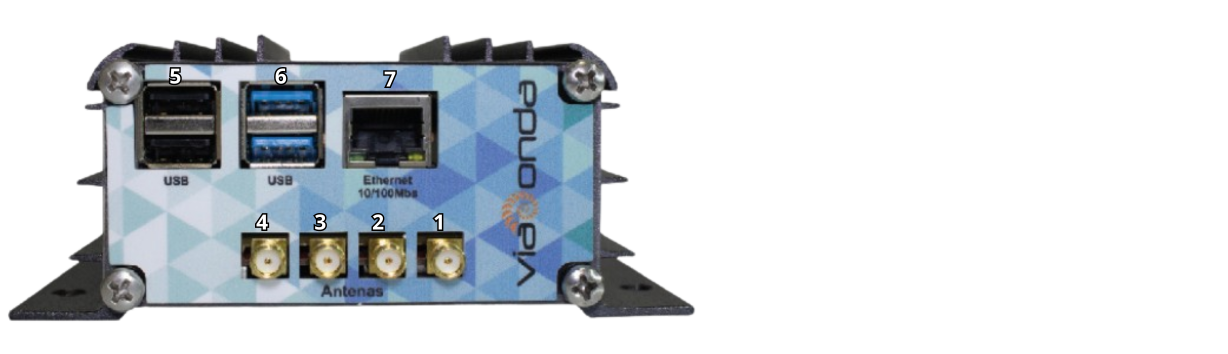
Front view
| Identif. | Description |
|---|---|
| 1 | Connector SMA of Antena 1 50ohms |
| 2 | Connector SMA of Antena 2 50ohms |
| 3 | Connector SMA of Antena 3 50ohms |
| 4 | Connector SMA of Antena 4 50ohms |
| 5 | Connector USB 2.0 |
| 6 | Connector USB 3.0 |
| 7 | Connector RJ45 for network 10/100Mbps |