Use Instructions
Reading Modes
The M-ID40 allows operation in 3 different modes, continuously, autonomous mode (inventory) and trigger mode (trigger). Each of the operating modes has specific operating characteristics, which can be better exemplified in the following topics.
Continuous mode
When in continuous mode, the M-ID40 enters uninterrupted reading mode, where it will send via network (either Ethernet or Wireless) each tag read in hexadecimal format.
This mode depends on the connection established with the reading software, if the communication is interrupted, it entry in waiting mode again, waiting for the command for reading restart.
Autonomous mode (inventory)
When in autonomous mode, or, inventory, the module will operate without the intervention of the software, in this case it will store in an internal buffer (Linux Model) all tags read and, after new connection to the software, as soon as it receives Buffer reading request will return through the network the full list of tags read during the inventory. Remembering that RFID-read labels are always made available by M-ID40 in hexadecimal format.
Trigger mode
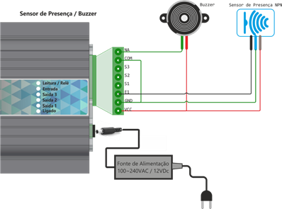
When in trigger mode, the module will only enter reading mode when it receives a pulse in the E1 pin in the interface connection. Detailing of the interfaces can be found in the input and output interfaces session. Operating in this mode, the reader, after receiving a signal in the E1 pin, will go into reading mode, and will remain until the pulse state in pin E1 changes state. For example, if the pulse lasts 5 seconds, the module will read the tags for a period of 5 seconds, awaiting the request for reading the buffer via command to return the list of read labels, also in hexadecimal format.
Diagrams
General Operating Diagram
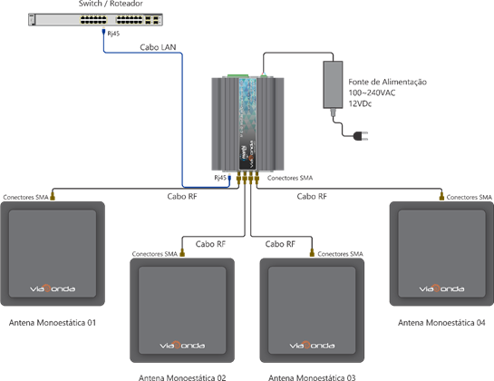
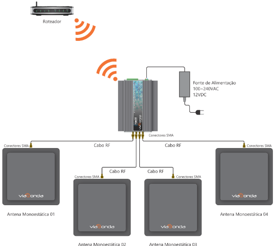
The diagrams presented above demonstrate the default installation of the M-ID40 module, with a maximum of 4 antennas, both using the Ethernet model and the Wifi model. When connecting the M-ID40 for the first time, it will be in operation Factory Mode, as described in factory settings. To change the operating mode, check the operating modes topic.
In order for the reader to operate correctly and read the RFID UHF labels, make sure there is at least one antenna properly connected to the equipment.
Depending on the reader's operation mode, with each new reading, it will automatically send the tag code read in hexadecimal formed through the communication method of each model, via Ethernet or Wifi.
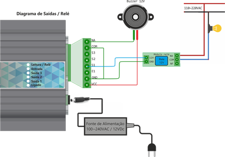
Buzzer and sensor(trigger mode) installation diagram
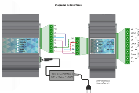
Output installation diagram (with the interface M-IDIO3)
Output installation diagram (Generic)
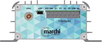
Connectors functionality table
| Identif. | Description |
|---|---|
| Power suply GND | Power input 0v (GND) |
| Power suply VCC | Power input 12Vdc |
| USB | Connector USB Type Mini For serial communication with the PC (The cable is not included) |
| Vin | Auxiliar Output 12Vdc |
| GND | Auxiliar Output GND |
| VCC | Auxiliar Output VCC |
| E1 | 12V input for sensor (trigger) |
| S1 | Auxiliar Output 1 12Vdc |
| S2 | Auxiliar Output 2 12Vdc |
| S3* | Auxiliar Output 3 12Vdc |
| COM | Common input Rele |
| NA | NA Rele Output |
*Available only in Linux and WiFi versions
Attention
Be sure to use the power supply sent with the reader so as not to cause damage to the hardware of the equipment.
Front View - Wifi Model
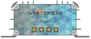
| Identif. | Description |
|---|---|
| 1 | Antenna SMA Connector 1 50ohms |
| 2 | Antenna SMA Connector 2 50ohms |
| 3 | Antenna SMA Connector 3 50ohms |
| 4 | Antenna SMA Connector 4 50ohms |
Front View – Ethernet Model
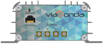
| Identif. | Description |
|---|---|
| 1 | Antenna SMA Connector 1 50ohms |
| 2 | Antenna SMA Connector 2 50ohms |
| 3 | Antenna SMA Connector 3 50ohms |
| 4 | Antenna SMA Connector 4 50ohms |
| 5 | RJ45 Connector for network 10/100Mbps |
Front View – Linux Model
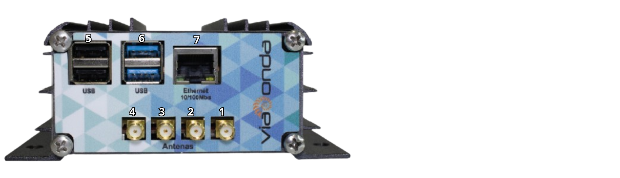
| Identif. | Description |
|---|---|
| 1 | Antenna SMA Connector 1 50ohms |
| 2 | Antenna SMA Connector 2 50ohms |
| 3 | Antenna SMA Connector 3 50ohms |
| 4 | Antenna SMA Connector 4 50ohms |
| 5 | USB Connector 2.0 |
| 6 | USB Connector 3.0 |
| 7 | RJ45 Connector for network 10/100Mbps |
Rear view Wifi, Ethernet and Linux models