Instructions for Use
General Operation Diagram
The diagram shown below demonstrates the standard installation of the M-ID40 - Light module. When powering on the M-ID40 - Light for the first time, it will be in factory operation mode.
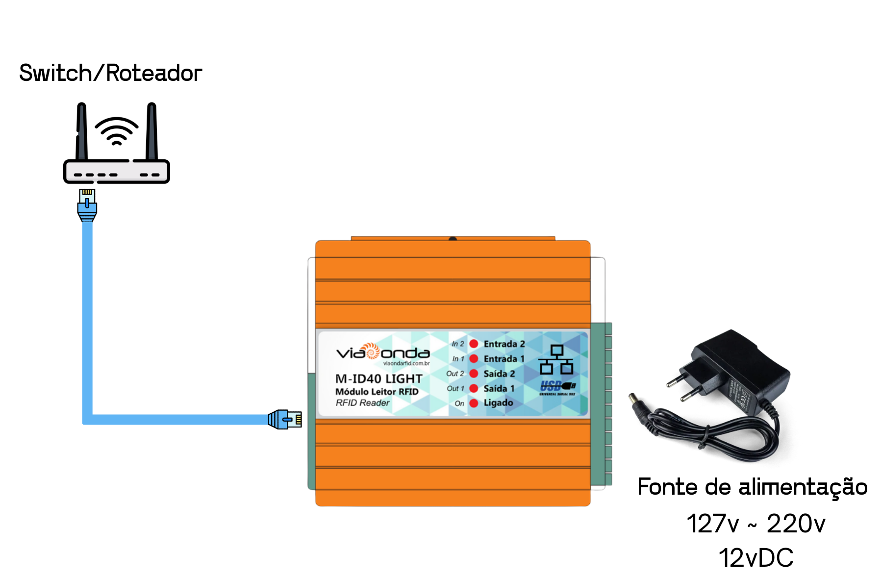
Attention
Make sure to use the power supply provided with the reader to avoid causing damage to the device hardware.
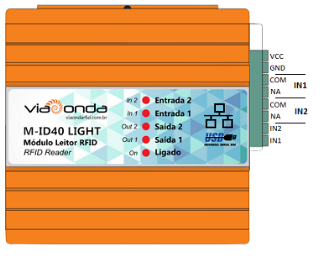
Descrição dos bornes
In the Ethernet model, radio frequency settings are configured through the SDK available for download at: restrito.viaondarfid.com.br.

SDK

Configurações do leitor
Conexão

To connect the reader to the SDK via TCP/IP, the default settings are:
IP: 192.168.0.10
Porta: 5000

Importante
The computer and the reader must be configured within the same IP range for the connection to be established.
Região
In the Region field, you can configure the frequency at which the reader will operate, either by selecting a fixed frequency or a range with a defined start and end.

Potência
In the Power field, the module's output power is adjusted from 0 dBm to 33 dBm, limiting the reading range as the power is reduced.

Antenas
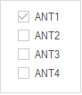
In Antenna config, you can select which antenna should be active or inactive for operation.

Also for reference, the reader has identification on the antenna connectors as shown in the image below.

In GPIO Operation, using the Get button retrieves which input or output is active, and the Set button is used to save any manual changes to the reader's input or output.

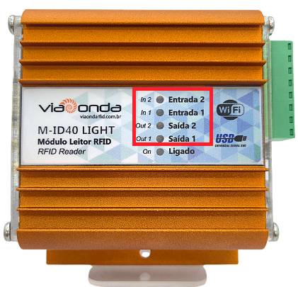
On the reader, it is also possible to identify which Inputs or Outputs are active through the identification LED.
At the top of the SDK, by selecting the EPCC1-G2 Test tab and below the Answer Mode tab, it is possible to perform reading tests with several configuration options. The reading is started by pressing the Start button.

In this field, it is possible to change the memory bank to be read. By clicking the Start button, the reading begins.

In this field, it is possible to select which antennas will be active during the reading.
In the Tag list area, the readings are received.

In the tag reading area, the information is displayed in columns, as follows:
NO.: Sequence number in which the tag was read.
EPC: EPC code read from the tag.
Count: Number of times the same tag was read.
RSSI: Tag response signal strength.
Antena(4-1): Antenna that performed the readings.
1: Antenna on connector 1
2: Antenna on connector 2
3: Antenna on connector 3
4: Antenna on connector 4
Translated/Prod. Code: Translated product code when integrated with a database.
:::
RSSI (Received Signal Strength Indicator) is a measure of the power level received by a wireless device antenna (tag). :::
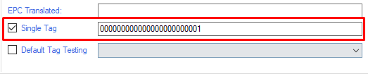
If you are using the software version with tag filtering, you will be able to filter the readings. To select the tag to be filtered, simply double-click with the left mouse button or type the full EPC in the text field. The Single Tag option must be checked for the filter to work.
At the top of the SDK, by selecting the EPCC1-G2 Test tab and below the Read/Write Tag tab, it is possible to write tags with several configuration options.

For writing, if there are other tags within the reader's range, it is possible to select and write only the chosen tag.

It is also possible to use a mask for reading and writing.

:::
To use the mask, the filled information must be in hexadecimal format.
:::
In this field, it is possible to read and write the tag by clicking Read to perform the reading and Write to write the tag with the new EPC entered in "Read/Write data".

TCP/IP settings are configured through a web browser using the reader's IP, or through the software available for download by accessing our restricted page at restrito.viaondarfid.com.br

:::
To configure via browser, the computer must be on the same IP range as the reader. By default, the reader's IP is 192.168.0.10.
User: admin
Password: admin
:::
USR Software Search Reader
On the initial screen, by clicking Search Device, the readers found on the network will be displayed.

:::
In some cases, for the reader to be detected, it is necessary to change the computer's IP settings to the same IP range as the reader. By default, the reader's IP is 192.168.0.10.
:::
Network Settings
After selecting the reader you want to configure, the configuration screen will appear as shown in the image below. On this screen, it is possible to change settings such as IP, Subnet Mask, Gateway, MAC Address, etc. After filling in the new information, simply click Save Config to save the new configuration and, after a few seconds, click Search Device again to verify that the settings were successfully saved.
